
How Engineers Select Globe Valves for Industrial Systems
TABLE OF CONTENTS
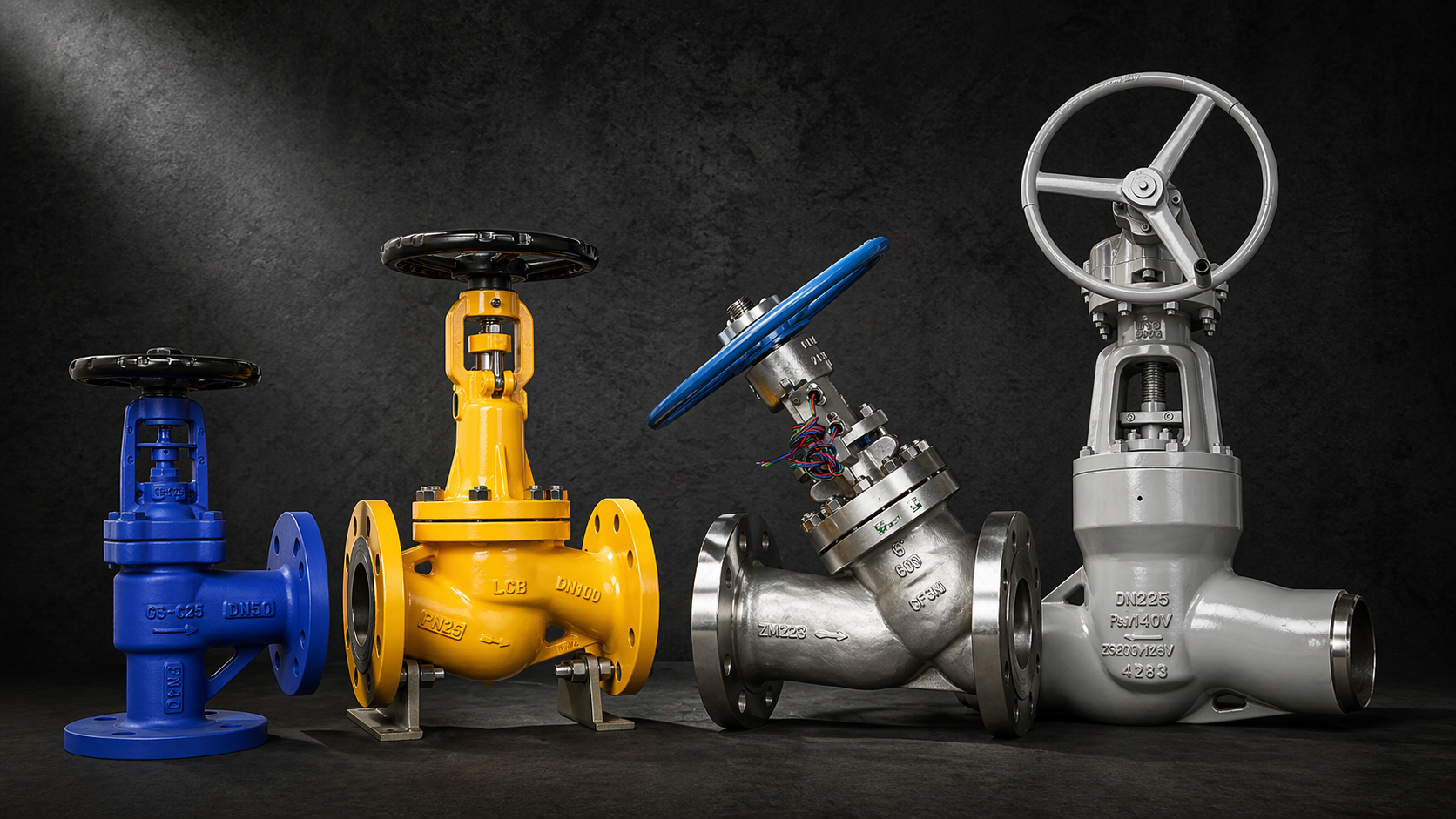
Straight pattern vs Y-pattern, Stellite trim, pressure-seal bonnet, Cv sizing — a practical globe valve selection guide for engineers and industrial procurement teams
Globe valves do something that gate valves and ball valves fundamentally cannot — they regulate flow accurately under repeated cycling conditions without destroying their seating surfaces in the process. The disc-to-seat geometry in a globe valve is specifically designed for partial opening under flow, which is why globe valves are the standard specification for steam drain control, boiler feed water regulation, desuperheater inlets, and pressure letdown applications where a gate valve would wire-draw its seats within months.
That said, globe valves are not a universal solution. They introduce higher pressure drop than gate or ball valves in the same bore size, and they’re not appropriate for applications where low pressure drop or full-bore pigging access is required. Getting the selection right means understanding both where globe valves belong and the engineering decisions that determine which type of globe valve fits the application.
This guide covers those decisions in the order that matters.
1. What Globe Valves Are Actually For
Globe valves are designed for throttling, flow regulation, and frequent open/close cycling. The disc moves along the valve centreline into or away from the seat, allowing precise control of flow area at any position between fully open and fully closed.
This geometry is what makes globe valves suitable for applications that would destroy a gate valve. In a gate valve, partial opening exposes the wedge face to high-velocity flow that erodes the seating surfaces — wire drawing. In a globe valve, the disc is designed to operate at partial lift, and the seating geometry distributes the flow forces in a way that allows repeated cycling without rapid seat degradation.
Where globe valves are not the right choice: large-bore low-frequency isolation duty where pressure drop matters (use a gate valve), fast quarter-turn shutdown service (use a ball valve), and applications requiring full-bore pigging access (neither globe nor gate valves are appropriate).
One common misconception is that globe valves can serve as control valves without actuator assistance. Manual globe valves are appropriate for occasional flow balancing and isolation. For precise automated process control — DCS-integrated pressure or flow regulation — a purpose-designed control valve with correct Cv sizing and an appropriate actuator is required. The two applications are related but not interchangeable.
2. Pressure Class Selection
Globe valve pressure class follows ASME B16.34, with the same pressure-temperature derating that applies to all steel valves — allowable working pressure decreases as temperature increases.
- Class 150 / PN16–25 — utility service, low-pressure steam, general plant piping below 260°C
- Class 300 / PN40–50 — medium pressure process and steam service
- Class 600 — higher pressure steam, boiler feed water, and refinery service; pressure-seal bonnet typically specified at this class and above in high-temperature applications
- Class 900 to 2500 — critical high-pressure service including main steam drain valves in large power plants, high-pressure boiler auxiliary systems, and refinery critical duty
For steam systems in particular, verify pressure-temperature ratings against ASME B16.34 for the specific material grade. A WCB carbon steel globe valve at Class 600 carries approximately 102 bar at 38°C — but this derates to around 73 bar at 400°C. If your boiler feedwater line operates at 80 bar and 400°C, a Class 600 WCB globe valve is undersized.
3. Body Material Selection
The material selection logic for globe valves mirrors gate valves — temperature and fluid chemistry drive the decision.
Carbon steel (ASTM A216 WCB / A105 forged) — standard for general steam, water, and non-corrosive process service up to approximately 425°C. The default specification for the majority of industrial globe valve applications.
Chrome-moly alloy steel (ASTM A217 WC6 — 1.25Cr-0.5Mo) — for elevated temperature service up to approximately 540°C, where carbon steel enters the creep range. Standard for boiler feed water control line globe valves and auxiliary steam system globe valves in power plants.
Higher chrome-moly alloy steel (ASTM A217 WC9 — 2.25Cr-1Mo) — for severe high-temperature service up to approximately 595°C. Specified for main steam drain globe valves and desuperheater inlet globe valves in supercritical and ultra-supercritical power plant applications where WC6 would be operating near its temperature limit.
Low-temperature carbon steel (ASTM A352 LCB / LCC) — for cryogenic and cold service applications where standard carbon steel impact properties are inadequate.
Stainless steel (ASTM A351 CF8M / CF3M) — for corrosive media, chemical process service, and applications where carbon steel corrosion would affect product quality or valve service life. CF8M is the standard stainless specification; CF3M where low-carbon content is needed to minimise sensitisation risk in welded installations.
Duplex stainless steel — for chloride-containing environments and seawater cooling system service where standard 316SS would suffer stress corrosion cracking.
WC6 and WC9 both require PWHT after welding — a practical fabrication and installation consideration for butt weld end globe valves in alloy steel.
4. Globe Valve Pattern — Straight, Y-Pattern, or Angle
The flow path geometry of a globe valve affects pressure drop, flow capacity, and suitability for different service conditions. This is a selection decision that often gets less attention than material or pressure class — but it directly affects valve performance.
Straight pattern (T-pattern) globe valves have the most common configuration — the flow path makes two 90° turns through the valve body, which creates relatively high pressure drop compared to other valve types. This is acceptable in most throttling and control applications where pressure drop across the valve is part of the system design intent. Straight pattern is the standard specification for steam drains, boiler feed water control, and general process throttling duty.
Y-pattern globe valves have a body configuration where the stem and seat are angled at approximately 45° to the pipe centreline, rather than 90°. This reduces the number of direction changes in the flow path and results in significantly lower pressure drop than a straight pattern globe valve in the same bore size. Y-pattern designs are preferred for high-pressure steam service where pressure drop needs to be minimised while still providing throttling capability, and for applications with high flow velocity where the straight pattern’s turbulence would cause accelerated seat erosion. The trade-off is a longer face-to-face dimension and higher cost than an equivalent straight pattern valve.
Angle globe valves change the flow direction by 90° — the inlet and outlet are at right angles to each other rather than in line. This is useful in corner piping configurations where an in-line valve would require additional bends, and in drain service where the valve connects a horizontal pipeline to a vertical drain line. Angle globe valves also provide lower pressure drop than straight pattern for a given bore size, because the flow makes only one direction change rather than two
5. Trim Material — This Is Where Globe Valve Service Life Is Actually Determined
In a globe valve, the disc and seat face are the components under the most mechanical and thermal stress. Getting trim material selection right is the difference between a valve that maintains sealing performance over years of cycling service and one that requires seat replacement after a single operating season.
Standard stainless steel trim (13Cr or 316SS) is appropriate for moderate temperature service in clean, non-erosive media — utility steam below 300°C, water service, and general process applications where cycling frequency is low.
Stellite hardfaced trim is the standard specification for high-temperature steam service and applications where the disc and seat face are subject to erosion, thermal cycling, or high contact stress. Stellite is a cobalt-chromium alloy applied as a weld overlay to the seating surfaces — it provides exceptional resistance to erosion, galling, and thermal fatigue that would rapidly degrade standard stainless steel trim in steam service. For globe valves on boiler feed water control lines, desuperheater inlets, and main steam drain service, Stellite-hardfaced trim is not a premium option — it’s the engineering-correct specification.
Tungsten carbide coated trim provides even higher hardness than Stellite, making it appropriate for severely erosive service — high-velocity steam with particulate contamination, abrasive slurry service, or applications where the pressure drop across the valve generates high fluid velocity at the seat face.
Trim hardness matching is an important consideration that is sometimes overlooked. If the disc is significantly harder than the seat face (or vice versa), the softer component wears preferentially. Matched hardness between disc and seat, or a deliberate hardness differential where the replaceable component is the softer one, extends overall trim life.
6. Bonnet Design — Bolted vs Pressure Seal
The bonnet design logic for globe valves is identical to gate valves.
Bolted bonnet is standard for Class 150 through Class 300, and is commonly used up to Class 600 in moderate temperature service. Adequate for most industrial globe valve applications. Subject to bolt relaxation at elevated temperatures — periodic retorquing during maintenance is required.
Pressure seal bonnet is the standard specification for Class 600 and above in high-temperature steam service. The design loads the bonnet gasket using internal pressure rather than bolt preload, so sealing performance improves as system pressure increases. This eliminates bolt relaxation as a failure mode and is why pressure seal bonnet globe valves are the engineering standard for power plant high-pressure auxiliary steam and boiler feed water applications.
For globe valves on main steam drains or desuperheater inlets at Class 900 and above, pressure seal bonnet construction is not optional — bolted bonnet designs at these conditions require impractical bolt retorquing intervals to maintain leak tightness.
7. Cv Sizing — Why It Matters More Than Most Buyers Realise
For globe valves used in flow regulation or control applications, correct Cv sizing is as important as material and pressure class selection.
Cv (flow coefficient) is a measure of a valve’s flow capacity at a given opening — defined as the flow rate in US gallons per minute of water at 60°F that produces a 1 psi pressure drop across the valve. The equivalent metric parameter is Kv.
An oversized globe valve operates predominantly in the nearly-closed position, where small changes in disc position produce large changes in flow rate. This creates control instability — the valve hunts between positions and never achieves stable regulation. It also concentrates flow velocity and turbulence at the minimum opening, causing accelerated seat erosion at the point of closest disc-to-seat contact.
An undersized globe valve cannot pass the required maximum flow rate, restricts system performance, and operates at near-full-open position where throttling control is poor.
Correct Cv sizing requires the actual process data: maximum and minimum required flow rates, inlet and outlet pressure, fluid phase and properties, and acceptable pressure drop across the valve at design conditions. A supplier who quotes a globe valve based on line size alone — without reviewing the process datasheet — is not sizing the valve correctly.
8. End Connection
Flanged ends (ASME B16.5) — standard for most plant piping. Removable for maintenance and inspection of disc and seat faces, which is a practical advantage of flanged globe valves over butt weld designs in throttling service where periodic seat inspection and reconditioning is part of the maintenance programme.
Butt weld ends — for permanent high-pressure piping where flanged joints are eliminated to reduce leak paths. Requires PWHT for alloy steel grades after installation welding. Seat inspection and reconditioning requires in-situ work or valve removal from the pipeline.
Socket weld ends — standard for small-bore high-pressure lines, typically DN50 and below.
9. Actuation
Handwheel — appropriate for manual flow balancing, drain service, and isolation duty where automated control is not required. Globe valves require multiple turns to open and close — the number of turns increases with valve size.
Gear operator — for large bore globe valves where handwheel torque is impractical, and for applications requiring precise positioning under high differential pressure.
Electric actuator — multi-turn electric actuators for remote operation and DCS integration. Position feedback via 4-20mA signal allows accurate valve position control from the control room.
Pneumatic actuator — for fast-response control applications and automated shutdown service. Diaphragm-type pneumatic actuators with positioners are the standard for globe-type control valves in process industries.
For any actuated globe valve, stem thrust calculation under maximum differential pressure conditions is required — a common error is sizing the actuator against normal operating conditions without checking whether it can generate sufficient thrust to seat the disc against maximum line pressure.
10. Industry-Specific Requirements
Power plants — high-pressure globe valves for boiler feed water control lines, steam drain service, desuperheater inlets, and turbine auxiliary systems. WC6/WC9 alloy steel body, Stellite-hardfaced trim, pressure seal bonnet, and butt weld ends are the standard specification package for Class 600 and above in steam service. These are not catalogue items — individual material certification and pressure testing documentation are baseline requirements.
Refineries — globe valves for pressure letdown stations, hydrocarbon process throttling, and utility steam service. API 623 governs design and testing requirements for globe valves in refinery and petrochemical service. Fugitive emission control — low-emission stem packing — is increasingly specified for volatile organic compound service.
Chemical plants — stainless steel or alloy material globe valves for corrosive process fluids, with PTFE or other chemically resistant packing and gasket materials for aggressive media.
Marine and offshore — seawater cooling system globe valves in duplex stainless steel or naval bronze, with corrosion-resistant trim for continuous seawater service.
11. Common Selection Mistakes
Using a gate valve for throttling service — the most common error in the field and the most predictable way to destroy a valve’s seating surfaces rapidly.
Specifying standard stainless steel trim for high-temperature steam service — Stellite hardfacing exists precisely because stainless steel trim degrades unacceptably in this application. The cost difference between standard and Stellite trim is small relative to the cost of seat replacement.
Sizing a globe valve based on line size rather than Cv calculation — oversized valves in control applications cause instability and accelerated wear; undersized valves restrict flow and provide poor controllability.
Ignoring cavitation risk in liquid pressure letdown service — when pressure drops significantly across a globe valve in liquid service, localised pressure can fall below vapour pressure, creating vapour bubbles that collapse destructively on downstream surfaces. Cavitation causes rapid erosion of disc and seat faces and downstream piping. Anti-cavitation trim designs exist for this application — specifying standard trim in a high pressure-drop liquid service is a specification error.
Undersizing the actuator by calculating stem thrust against normal operating conditions only — the valve needs to seat against maximum differential pressure, not average operating differential pressure.

HD Flowtech — Globe Valve Supply and Technical Support
HD Flowtech manufactures and supplies industrial globe valves for power generation, oil and gas, chemical, and general process applications — straight pattern, Y-pattern, and angle designs; bolted and pressure seal bonnets; standard stainless and Stellite hardfaced trim; carbon steel, alloy steel, stainless steel, and duplex materials; across ASME Class 150 to 2500.
We review your system operating conditions, process datasheet, and Cv requirements before recommending a specification — not after you’ve placed the order.
Send us your pressure class, temperature, fluid, flow rate, and bore size. We’ll come back with the right specification and pricing.
RELATED ARTICLES
WCB vs WC6 vs WC9 Valve Materials: Engineering Guide for Steam Service
WCB, WC6, and WC9 valve body materials compared — temperature limits, chromium-molybdenum content, creep resistance, PWHT requirements, and steam service selection guidance for engineers.
How to Choose a Reliable Power Plant Valve Supplier for Saudi Arabia
How to choose a power plant valve supplier for Saudi Arabia — gate valves, globe valves, ASME standards, MTRs, and API 598 test certificates explained.
Common Valve Failures in Steam Lines: Causes, Prevention & Best Solutions
Seat leakage, thermal cracking, water hammer — the most common steam line valve failures explained, with material selection and engineering prevention guidance.
TABLE OF CONTENTS
RELATED ARTICLES
WCB vs WC6 vs WC9 Valve Materials: Engineering Guide for Steam Service
WCB, WC6, and WC9 valve body materials compared — temperature limits, chromium-molybdenum content, creep resistance, PWHT requirements, and steam service selection guidance for engineers.
How to Choose a Reliable Power Plant Valve Supplier for Saudi Arabia
How to choose a power plant valve supplier for Saudi Arabia — gate valves, globe valves, ASME standards, MTRs, and API 598 test certificates explained.
Common Valve Failures in Steam Lines: Causes, Prevention & Best Solutions
Seat leakage, thermal cracking, water hammer — the most common steam line valve failures explained, with material selection and engineering prevention guidance.