
Pipeline Filtration & Steam Trap Selection for Industrial Applications
TABLE OF CONTENTS
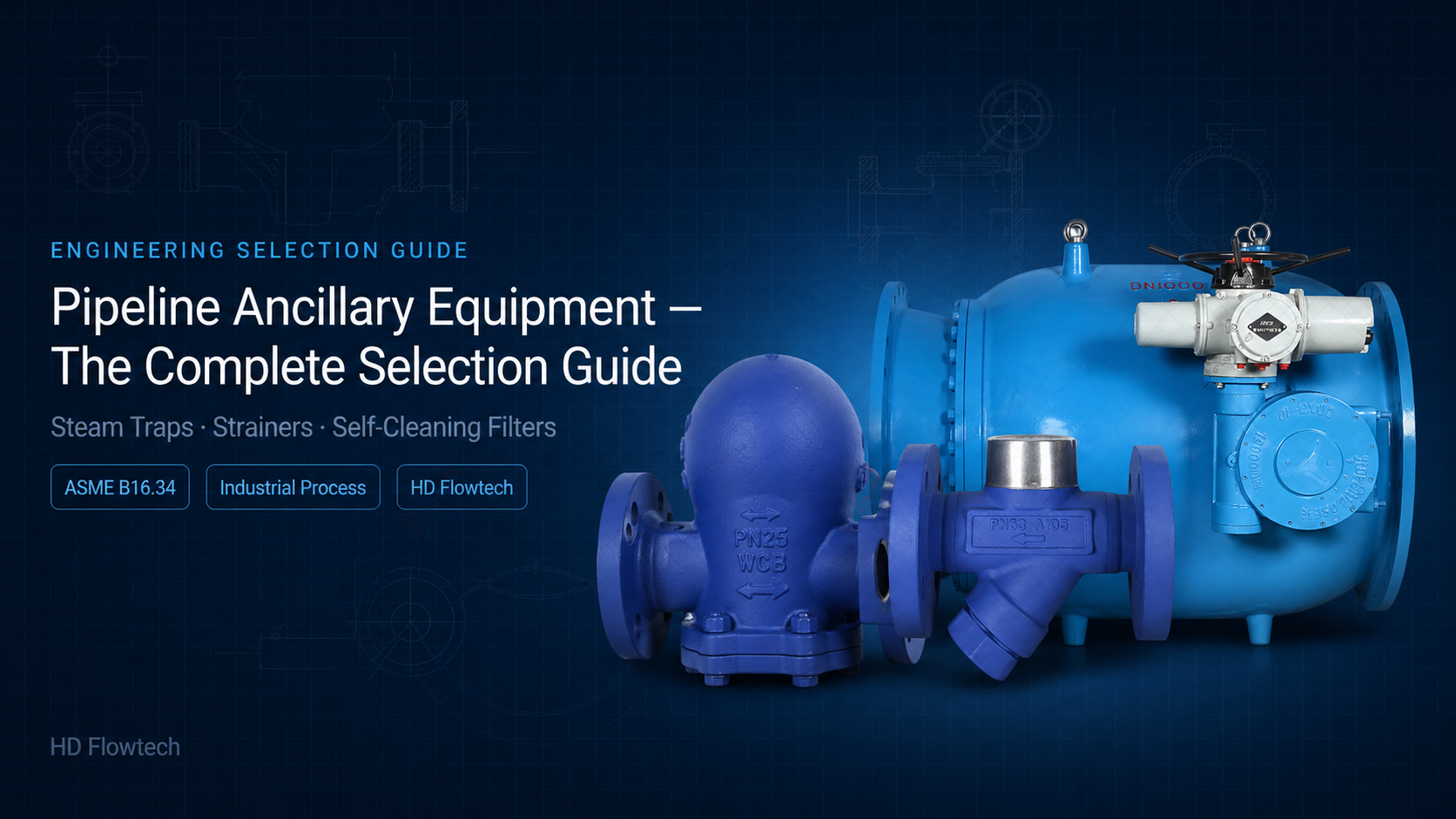
Ball float steam traps, Y-type strainers, and self-cleaning backwash filters — a practical selection guide for engineers and industrial procurement teams.
Valves get most of the attention in industrial piping design. But the ancillary equipment sitting alongside them — steam traps, strainers, and filters — is equally critical to system performance and longevity. Specify the wrong steam trap and you waste energy or flood your steam mains. Miss the strainer upstream of a control valve and you damage the trim within weeks. Skip the filter on a recirculating water system and fouling builds until the system chokes.
This guide covers the three most common categories of pipeline ancillary equipment, how each works, and the key selection decisions for each — in the context of real industrial applications.
Why Ancillary Equipment Gets Underspecified
The pattern is consistent across plant types: valves and pressure vessels are specified carefully, with detailed datasheets and material reviews. Steam traps are selected from a catalogue by a junior engineer in the last week before issue for construction. Strainers are added to the line list as an afterthought. Filters are sometimes omitted entirely until commissioning reveals the problem.
The consequences are predictable. Steam traps that are oversized or incorrectly typed flood steam mains with condensate, cause waterhammer, and damage downstream equipment. Strainers sized for normal flow velocity collapse their screens on first startup when debris is heaviest. Filters with manual cleaning intervals get missed during plant turnarounds and block solid.
Treating ancillary equipment with the same engineering rigour as the valves around it is not overengineering — it is the baseline for a system that performs as designed from day one.
Part 1: Steam Traps
What a steam trap does
A steam trap is an automatic drain valve that removes condensate and non-condensable gases from a steam system without allowing live steam to pass. Condensate forms continuously as steam gives up heat to the process — if it isn’t removed, it accumulates in steam mains and heat exchangers, reducing heat transfer efficiency and causing waterhammer as high-velocity steam meets slugs of water.
The steam trap must open to discharge condensate, then close before steam follows it out. How it achieves this depends on the trap type.
Ball float steam traps — how they work and where they belong
A ball float steam trap uses a hollow stainless steel ball that rises and falls with the condensate level inside the trap body. As condensate accumulates, the rising float opens a valve to discharge it. When the float drops — because the condensate level falls and steam is present — the valve closes. A separate thermostatic air vent in the trap body purges non-condensable gases on startup.
This continuous modulating action makes ball float traps the correct choice for process heat exchangers, heating coils, and any application where condensate forms continuously and needs to be removed immediately. The trap responds to condensate level rather than temperature difference, so it drains promptly without backing up condensate into the heat transfer surface.
Key selection parameters for ball float steam traps:
Pressure differential across the trap is the primary sizing parameter — the trap must be able to discharge condensate against the backpressure in the condensate return line. Never size a steam trap on inlet pressure alone; the differential between inlet and outlet determines discharge capacity.
Condensate load must be calculated for the application — startup load (when cold equipment is being brought up to temperature) is typically several times higher than running load. Size the trap for startup conditions if continuous condensate removal during startup is required, or accept that startup will be slower.
Body material follows the steam system pressure class and fluid — carbon steel for standard steam service, stainless steel for clean steam, chemical, and pharmaceutical applications.
Maximum allowable pressure (MAP) must exceed the steam system design pressure, not just normal operating pressure. Steam pressure can exceed normal during startup or following pressure upsets.
Common steam trap selection mistakes
Selecting trap type based on familiarity rather than application. Ball float traps are excellent for continuous condensate loads but are not the right choice for steam tracing or steam mains drainage where condensate forms intermittently — thermostatic or inverted bucket traps are more appropriate for those duties.
Ignoring backpressure. A trap sized at zero backpressure will underperform severely when installed on a pressurised condensate return system. Always confirm the condensate return header pressure before sizing.
Over-specifying trap size. Oversized steam traps cycle infrequently, wear their seats through repeated hard opening and closing, and are more likely to fail open — discharging live steam into the condensate system.
Part 2: Strainers
What a strainer does
A strainer is a mechanical filter installed in a pipeline to remove solid particles — pipe scale, weld slag, gasket debris, rust, and process contamination — from the fluid stream before it reaches downstream equipment. Control valves, pumps, meters, heat exchanger tubes, and steam traps are all vulnerable to particulate damage. A strainer upstream of each protects the equipment and extends its service life.
Strainers are not fine filtration — they remove particles above a defined mesh size, not dissolved contaminants or fine suspensions. The distinction matters: specifying a strainer where a filter is required will not solve the contamination problem.
Y-type strainers — configuration and selection
A Y-type strainer has a body shaped like the letter Y, with the strainer screen element in the angled leg. Flow enters the main bore, passes through the screen, and exits — particles too large to pass through the mesh are retained in the screen pocket. The screen is accessed for cleaning by removing a plug or bolted cover at the end of the angled leg.
Y-type strainers are the most common strainer configuration in process plant. They are compact, available in a wide range of pressure classes and materials, suitable for horizontal and vertical installation, and can be cleaned in-line without removing the strainer from the pipe.
Key selection parameters for Y-type strainers:
Screen mesh size (or perforation size) is the primary process selection parameter. Mesh size must be chosen relative to the particle size that would damage the downstream equipment — not made as fine as possible. Excessively fine screens block rapidly in normal service and collapse under differential pressure on startup. Typical mesh sizes for protecting control valves are 40–60 mesh; for pump protection, 20–40 mesh; for steam traps, 100 mesh.
Free area ratio — the ratio of open screen area to pipe bore area — determines how quickly the strainer differentialpressure rises as the screen loads with debris. A higher free area ratio means longer service intervals between cleaning. Y-type strainers typically have a free area ratio of 2:1 to 3:1, which is adequate for most applications.
Pressure drop across a clean strainer must be within acceptable limits for the system. Confirm clean pressure drop at maximum flow rate — not just at normal operating conditions.
Body material and pressure class follow the piping system specification. Y-type strainers are available in carbon steel, stainless steel, and duplex stainless across ASME Class 150 to 1500. Specify the same material standard as the surrounding piping — not a lower grade on cost grounds.
Blow-down connection — a small valve on the screen pocket — allows partial flushing of accumulated debris without full disassembly. Specify this for applications where screen cleaning intervals are frequent or where removing the screen cover is inconvenient.
Common strainer selection mistakes
Selecting screen mesh size too fine for the application. A 100-mesh screen on a cooling water line will block within days on initial startup when construction debris is present. Startup strainers — temporary strainers installed for commissioning, then removed — should be specified with coarser mesh than permanent strainers.
Ignoring startup debris loads. New pipeline systems contain weld slag, millscale, and other construction debris that creates a short, heavy particle loading in the first hours of operation. Temporary startup strainers with easily replaceable screens should be installed upstream of sensitive equipment for the commissioning period.
Installing Y-type strainers in vertical downward flow without confirming screen orientation. In vertical installation, the screen pocket must point downward — so that collected debris falls away from the screen rather than resting against it. Installing a Y-type strainer with the screen pocket pointing upward in vertical flow means debris accumulates on the screen face and blocks rapidly.
Specifying strainer size only on line size, without checking velocity through the screen. At high flow velocities, differential pressure across a loaded screen can collapse the screen element. Confirm that the screen can withstand the maximum differential pressure that could develop between cleanings.
Part 3: Automatic Self-Cleaning Backwash Filters
What a backwash filter does — and when it’s needed
A self-cleaning backwash filter removes suspended solids from a liquid stream continuously and automatically, without requiring the system to be shut down or taken offline for cleaning. Unlike a Y-type strainer — which must be manually cleaned at intervals — a backwash filter monitors its own differential pressure and initiates a backwash cycle when the filter element begins to load.
During backwash, a portion of the clean filtered water is reversed through a small section of the filter element, flushing accumulated debris out through a drain connection. The rest of the filter element remains in service throughout the backwash cycle, so filtration is continuous. The entire cycle takes seconds and repeats automatically as needed.
Backwash filters are specified where continuous, unattended filtration is required, where shutdown for manual cleaning is unacceptable, or where particle loading is high enough that a strainer would require cleaning at impractically short intervals. Cooling water systems, irrigation, fire protection, and large industrial water treatment applications are the primary use cases.
Key selection parameters for self-cleaning backwash filters
Filtration degree (micron rating) defines the smallest particle size that the filter will reliably remove. Backwash filters are available in filtration degrees from approximately 25 microns to 3,000 microns. Selection must be based on the particle size that would cause problems downstream — protect heat exchanger tubes, nozzles, or spray headers at the appropriate micron rating for those components, not at an arbitrarily fine level that would cause excessive backwash frequency.
Flow rate is the primary sizing parameter. The filter must be sized to handle maximum system flow at an acceptable pressure drop across a clean element. Undersizing the filter body creates excessive velocity through the element and high clean pressure drop.
Backwash trigger — typically a differential pressure switch set at a defined pressure rise across the filter element, with a timer backup to initiate periodic backwash even if differential pressure remains low. Both triggers should be set and verified during commissioning.
Backwash flow rate and duration must be sufficient to effectively flush the element. The backwash drain connection and downstream disposal point must be sized for the peak backwash flow, which is typically higher than the normal filtrate flow rate through the backwash valve.
Actuator type for the backwash mechanism — electric or pneumatic — follows the available utilities at the installation point and the required response speed. Electric actuators are standard for most installations. Pneumatic actuators are preferred where power supply is unreliable or where faster backwash valve operation is required.
Body material and pressure class follow the fluid chemistry and system design pressure. Carbon steel is standard for cooling water and general industrial service. Stainless steel for potable water, chemical service, and applications where iron contamination of the filtered water must be avoided.
Common backwash filter selection mistakes
Selecting filtration degree too fine for the fluid quality. A filter rated at 50 microns on a heavily contaminated cooling water system will backwash continuously, wearing the mechanism and reducing effective filtration time. Match filtration degree to the actual requirement — protect the downstream equipment at the coarsest level that achieves the objective.
Undersizing the backwash drain line. If the drain cannot handle peak backwash flow, the backwash cycle is ineffective — debris is disturbed but not fully flushed, and element loading accelerates. Size the drain for peak backwash flow rate, not average system flow.
Omitting a bypass. Backwash filters require periodic maintenance — motor replacement, seal replacement, element inspection. Without a bypass, maintenance requires a system shutdown. Specify an isolation and bypass arrangement for any filter on a continuous-duty system.
Ignoring the differential pressure rise at end-of-life. As the filter element ages, baseline differential pressure rises. The backwash trigger setpoint must be reviewed relative to the clean element pressure drop — if the trigger is set too close to clean pressure drop, the filter backwashes constantly from early in its life.
Putting It Together — System-Level Thinking
Steam traps, strainers, and backwash filters don’t operate in isolation. In a typical industrial plant, they appear together in predictable combinations:
A steam system will have Y-type strainers upstream of steam traps (to protect the trap seat from pipe scale), ball float steam traps on heat exchangers and process equipment, and strainers again on the condensate return before it re-enters the boiler feedwater system.
A cooling water system will have a self-cleaning backwash filter on the main supply header, Y-type strainers immediately upstream of individual heat exchangers and control valves, and potentially finer strainers or filters on instrumentation and analyser sample lines.
A process water treatment system will sequence coarser strainers ahead of fine filters, protecting the fine filter elements from premature loading by large particles.
The system-level question to ask is: what is the particle load at each point in the system, what downstream equipment needs protecting at that point, and what cleaning or maintenance interval is acceptable? The answer to those three questions defines the correct equipment type, filtration degree, and configuration at each location — not the equipment type that was used on the last project, and not the cheapest option from the catalogue.

HD Flowtech — Ball Valve Supply and Technical Support
HD Flowtech supplies ball float steam traps, Y-type strainers, and automatic self-cleaning backwash filters for power generation, oil and gas, chemical, water treatment, and general process applications — in carbon steel, stainless steel, and duplex construction across a full range of pressure classes. Send us your flow conditions, fluid, and system design pressure. We’ll come back with the right specification and pricing.
RELATED ARTICLES
WCB vs WC6 vs WC9 Valve Materials: Engineering Guide for Steam Service
WCB, WC6, and WC9 valve body materials compared — temperature limits, chromium-molybdenum content, creep resistance, PWHT requirements, and steam service selection guidance for engineers.
How to Choose a Reliable Power Plant Valve Supplier for Saudi Arabia
How to choose a power plant valve supplier for Saudi Arabia — gate valves, globe valves, ASME standards, MTRs, and API 598 test certificates explained.
Common Valve Failures in Steam Lines: Causes, Prevention & Best Solutions
Seat leakage, thermal cracking, water hammer — the most common steam line valve failures explained, with material selection and engineering prevention guidance.
TABLE OF CONTENTS
RELATED ARTICLES
WCB vs WC6 vs WC9 Valve Materials: Engineering Guide for Steam Service
WCB, WC6, and WC9 valve body materials compared — temperature limits, chromium-molybdenum content, creep resistance, PWHT requirements, and steam service selection guidance for engineers.
How to Choose a Reliable Power Plant Valve Supplier for Saudi Arabia
How to choose a power plant valve supplier for Saudi Arabia — gate valves, globe valves, ASME standards, MTRs, and API 598 test certificates explained.
Common Valve Failures in Steam Lines: Causes, Prevention & Best Solutions
Seat leakage, thermal cracking, water hammer — the most common steam line valve failures explained, with material selection and engineering prevention guidance.